Minolta SRT 101B Manual: A Comprehensive Guide
This guide compiles resources for the Minolta SRT 101B, including service manuals, repair articles, and downloadable PDFs for both users and technicians․
The Minolta SRT 101B, a cornerstone of 35mm SLR photography, remains popular due to its reliability and excellent optics․ This manual serves as a central resource for understanding and maintaining this classic camera․ Numerous downloadable resources exist, including comprehensive service manuals – available as PDFs from sources like the Internet Archive – detailing intricate repair procedures․
These manuals, often exceeding 40 pages, cater to both enthusiasts and professional repair technicians․ Beyond repair, instruction manuals and parts listings are readily accessible, aiding in general operation and component identification․ The SRT 101B’s enduring appeal necessitates readily available documentation for continued use and preservation․
History and Significance of the SRT 101B
Introduced in 1970, the Minolta SRT 101B represented a significant advancement in accessible SLR technology․ Its success stemmed from a blend of robust construction, accurate metering, and a wide range of compatible lenses․ The availability of detailed service manuals, like those archived online, contributed to its longevity, enabling repairs and maintenance long after production ceased․
These manuals, often sourced from professional photographic journals, demonstrate the camera’s importance within the repair community․ The SRT 101B wasn’t just a camera; it was a platform for learning and a testament to Minolta’s engineering prowess․ Its enduring presence is supported by continued documentation and parts availability․
Key Features and Specifications
The Minolta SRT 101B boasts a mechanically controlled focal plane shutter with speeds from 1 to 1/1000th of a second, plus Bulb․ It features a center-weighted metering system utilizing a CdS photocell․ Interchangeable lenses with the Minolta SR mount are fully compatible, expanding creative possibilities․ Service manuals detail adjustments for these lenses․
Key specs include accepting standard 35mm film, offering a self-timer, and a hot shoe for external flash․ Downloadable manuals provide detailed schematics and troubleshooting guides․ The camera’s robust build and readily available documentation, including repair articles, solidify its place as a classic․

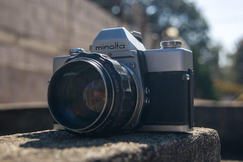
Understanding the Camera Body
Detailed service manuals illustrate the SRT 101B’s construction, aiding in disassembly, repair, and understanding the function of each component within the camera․

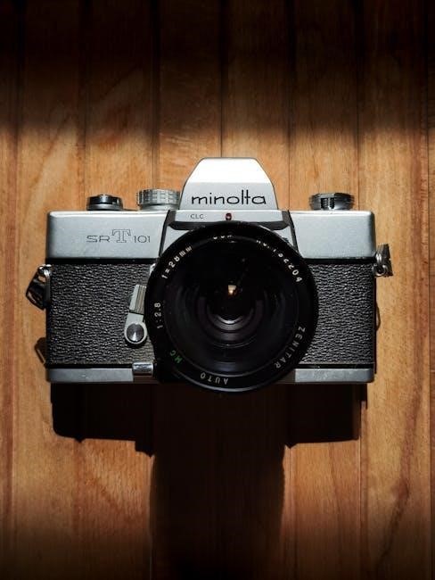
External Controls and Their Functions
The Minolta SRT 101B features a robust set of external controls, meticulously detailed within available service manuals and guides․ These resources illustrate the precise operation of the shutter speed dial, aperture ring on compatible lenses, and the film advance lever․ Understanding the self-timer mechanism is also covered, alongside the rewind crank and its function in retrieving exposed film․
Detailed diagrams showcase the location and purpose of each control, assisting in both operation and potential repair․ The manuals clarify the interaction between these controls and the camera’s internal metering system․ Furthermore, they provide insights into the functionality of the depth-of-field preview lever and its impact on image composition․ Accessing these guides is crucial for mastering the SRT 101B’s capabilities․
Viewfinder System and Focusing Aids
The Minolta SRT 101B’s viewfinder is central to accurate focusing and composition․ Service manuals detail its features, including the split-image rangefinder at the center, crucial for achieving sharp images․ Microprism collars surrounding the split-image aid in fine-tuning focus, particularly with faster lenses․ These focusing aids are thoroughly explained in downloadable guides․
The viewfinder also displays essential exposure information, integrated with the camera’s metering system․ Understanding how to interpret these indicators is key to proper exposure control․ Manuals illustrate the viewfinder’s layout and explain how different lens focal lengths affect the visible field of view․ Proper utilization of these features, as outlined in the documentation, ensures optimal photographic results․
Film Loading and Advance Mechanism
The Minolta SRT 101B utilizes a traditional film loading system, detailed in available service manuals and guides․ Correct film loading is essential for preventing damage to the camera or film․ Instructions cover opening the back, inserting the film canister, and threading the film leader onto the take-up spool․
The camera features a single-stroke film advance lever, offering smooth and reliable film transport․ Manuals explain the proper technique for advancing the film and resetting the frame counter․ Troubleshooting sections address common issues like film jamming or incorrect frame counting․ Understanding the mechanics, as described in the documentation, ensures consistent and trouble-free film handling․
Operation and Shooting Modes
The SRT 101B offers full manual operation, allowing precise control over aperture and shutter speed for creative photographic expression, as detailed in guides․
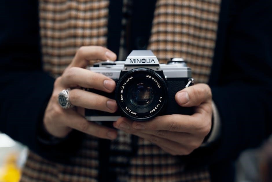
Setting Aperture and Shutter Speed
The Minolta SRT 101B operates in fully manual mode, demanding direct control over both aperture and shutter speed for proper exposure․ The aperture ring, located on the lens, adjusts the lens opening, influencing depth of field and light intake․ Aperture is typically indicated in f-stops (e․g․, f/2․8, f/8)․
Shutter speed is set using the dial on the camera body, controlling the duration of light exposure on the film․ Common speeds range from 1 second to 1/1000th of a second, plus Bulb (B) for extended exposures․ Understanding the interplay between aperture and shutter speed is crucial; wider apertures and slower shutter speeds allow more light, while narrower apertures and faster speeds allow less․
Referencing the camera’s metering system (discussed elsewhere) assists in determining appropriate settings, but ultimately, the photographer makes the final decisions for desired creative effects․
Metering System and Exposure Control
The Minolta SRT 101B features a Center-Weighted Averaging (CWA) metering system, meaning it primarily measures light from the center of the frame, with diminishing sensitivity towards the edges․ A needle within the viewfinder indicates exposure status: “+“ signifies overexposure, “-” underexposure, and centered, correct exposure․
To utilize the meter, set the desired shutter speed, then adjust the aperture ring on the lens until the needle aligns with the center mark․ Alternatively, set the aperture first and adjust the shutter speed․ This system requires understanding the relationship between ISO, aperture, and shutter speed for accurate results․
Remember the meter responds to the light it sees, so strongly backlit scenes or unusual lighting conditions may require exposure compensation – manually adjusting settings beyond the meter’s reading․
Using the Self-Timer
The Minolta SRT 101B’s self-timer is activated by a lever located on the left side of the camera body, below the shutter speed dial․ Lifting this lever fully initiates a roughly 10-second delay before the shutter releases․ A small red lamp on the front of the camera illuminates during the countdown, visually indicating the remaining time․
To use the self-timer, compose your shot, focus, and then lift the self-timer lever․ Gently press the shutter button; the lever will remain engaged, and the timer will begin․
Ensure the camera is stable – use a tripod if possible – to avoid blur during the exposure․ The self-timer is ideal for group photos or situations where you need to be included in the frame․
Maintenance and Troubleshooting
Proper care ensures longevity․ This section details cleaning, storage, common issues, solutions, and battery care for your Minolta SRT 101B camera․
Cleaning and Storage
Maintaining your Minolta SRT 101B requires gentle cleaning practices․ Use a soft brush to remove dust from the body and lens․ Avoid harsh chemicals or solvents, opting instead for a microfiber cloth lightly dampened with lens cleaning solution․ Regularly check the film chamber for debris․
Proper storage is crucial for preventing damage․ When not in use, store the camera in a cool, dry place, away from direct sunlight and extreme temperatures․ Consider using a camera bag or case for added protection․ Remove batteries during extended storage to prevent corrosion․ Periodically exercise the shutter and advance mechanism to keep internal parts functioning smoothly․ A clean and well-stored camera ensures reliable performance for years to come․
Common Issues and Solutions
Several issues can arise with the Minolta SRT 101B․ A sticky shutter often results from aged lubricants; professional cleaning is recommended․ Light leaks can occur due to deteriorated light seals, requiring replacement․ Erratic meter readings may indicate a faulty battery or corrosion in the battery compartment – ensure proper battery type and clean contacts․
Film advance problems often stem from dried grease․ If the camera fails to load film, carefully inspect the take-up spool and film path․ Resources like the Internet Archive and repair articles from the Society of Photo-Technologists Journal offer detailed troubleshooting guidance․ Factory service manuals provide in-depth repair procedures, though some repairs are best left to qualified technicians․
Battery Replacement and Care
The Minolta SRT 101B utilizes a PX28 or equivalent 1․5V battery to power its metering system․ Battery replacement is straightforward, accessing the compartment on the camera’s bottom․ Always use the correct voltage; incorrect batteries can damage the circuitry․ Regularly check the battery compartment for corrosion, cleaning with a cotton swab and isopropyl alcohol if necessary․
Proper battery care extends its lifespan․ Remove the battery when the camera is stored for extended periods to prevent leakage․ Avoid mixing old and new batteries․ While the SRT 101B is largely mechanical, a functioning battery ensures accurate light metering, crucial for proper exposure․ Refer to the service manual for detailed diagrams of the battery compartment and related components․

Advanced Techniques
Explore depth of field control, external flash usage, and lens compatibility for maximizing the Minolta SRT 101B’s potential, enhancing photographic creativity and skill;
Depth of Field Control
Mastering depth of field is crucial for impactful photography with the Minolta SRT 101B․ Aperture selection directly influences the area in focus – wider apertures (smaller f-numbers like f/2․8) create shallow depth of field, ideal for isolating subjects with blurred backgrounds․ Conversely, narrower apertures (larger f-numbers like f/16) yield greater depth of field, keeping more of the scene sharp․
Consider the lens’s focal length; longer focal lengths naturally compress depth of field․ Focusing distance also plays a role; closer focusing distances result in shallower depth of field․ Experiment with these settings to creatively control what’s in focus and draw the viewer’s eye․ Understanding these relationships allows for artistic expression and precise image control with your SRT 101B․
Using External Flash
The Minolta SRT 101B features a hot shoe for connecting external flash units, expanding your lighting capabilities beyond the camera’s built-in limitations․ Ensure the flash unit is compatible with the camera’s sync speed (typically 1/60th of a second) to avoid dark bands across your images․
Set the camera to ‘X’ sync mode․ Adjust flash power based on the distance to your subject and desired effect․ Consider using a flash bracket for off-camera flash techniques, allowing for more creative lighting angles․ Diffusers can soften the flash output, reducing harsh shadows․ Remember to test your flash setup to achieve proper exposure and desired results with your SRT 101B․
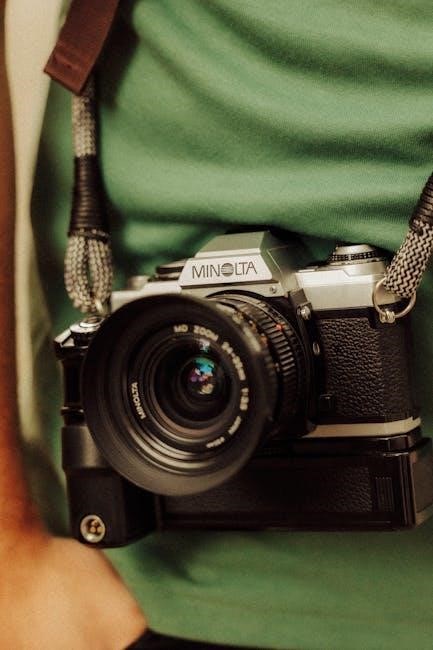
Lens Compatibility and Usage
The Minolta SRT 101B utilizes the Minolta SR mount, offering compatibility with a vast range of Minolta lenses produced over several decades․ This includes both manual focus lenses and early autofocus lenses (though autofocus functionality won’t be available)․ Adapters also exist to mount lenses from other systems, expanding your options further․
When using adapted lenses, ensure proper aperture control and focusing․ Pay attention to lens coatings and quality for optimal image results․ Regularly clean lens elements to maintain clarity․ The SRT 101B’s stop-down metering requires you to set the desired aperture on the lens before metering, ensuring accurate exposure․
Repair and Service Information
Locate factory service manuals and repair resources online, alongside articles from the Society of Photo-Technologists Journal detailing SRT-101 servicing procedures․
Locating Service Manuals and Repair Resources
Finding comprehensive repair information for the Minolta SRT 101B requires exploring several online avenues․ The Internet Archive hosts a digitized version of the Minolta SRT 101 Service Manual, readily available for download and viewing․ Additionally, specialized camera repair websites and forums often archive factory service manuals, including those for the SRT series․
The Society of Photo-Technologists Journal featured articles detailing servicing procedures for this camera model․ Searching for these articles can provide valuable insights into common repair issues and their solutions․ PDFs for related models like the Minolta XK and other SRT variants (102, 202, 303) may contain overlapping information useful for diagnostics․ Remember to verify compatibility before applying procedures from other models․
Common Repair Procedures (Based on Available Documentation)
Based on available resources, typical repairs for the Minolta SRT 101B often involve light seal replacement due to foam degradation over time․ Shutter mechanisms may require cleaning and lubrication to address sticking or inaccurate timing․ Metering system checks are crucial, potentially needing adjustments or component replacement if readings are consistently off․
The service manual details procedures for disassembling the camera for access to internal components․ Careful attention to screw locations and wiring is essential during reassembly․ Focusing screen adjustments and viewfinder cleaning are also common tasks․ Repair articles from the Society of Photo-Technologists Journal offer specific guidance on troubleshooting and resolving common issues encountered with this model․
Resources for Parts and Accessories
Finding parts for the Minolta SRT 101B can involve several avenues․ Online auction sites frequently list used components, including light seals, winding levers, and even complete camera bodies for parts․ Specialized camera repair shops often stock common replacement parts or can source them upon request․
Regarding accessories, original Minolta lenses compatible with the SRT 101B are readily available on the used market․ Lens service manuals, though potentially harder to find, can aid in their maintenance․ General AF lens service information may also prove useful․ Exploring online forums and communities dedicated to vintage cameras can connect you with sellers and enthusiasts offering parts and advice․
Resources and Further Learning
Expand your knowledge with online forums, recommended books, and downloadable manuals – essential resources for mastering the Minolta SRT 101B and its operation․
Online Forums and Communities
Engage with fellow Minolta SRT 101B enthusiasts online to share experiences, ask questions, and find solutions to common issues․ Several dedicated forums and photography communities offer valuable support for owners of this classic camera․ The Internet Archive hosts a digitized version of the Minolta SRT 101 service manual, readily available for download and reference․ These platforms often contain detailed discussions on repair procedures, lens compatibility, and advanced techniques․
Users frequently share scanned copies of original manuals and repair articles, supplementing the official documentation․ Participating in these communities provides access to a wealth of collective knowledge, assisting with troubleshooting and maintenance․ Explore these resources to deepen your understanding and enjoyment of the Minolta SRT 101B․
Recommended Books and Articles
While dedicated books solely focused on the Minolta SRT 101B are scarce, resources covering classic 35mm SLR photography and Minolta’s lens systems prove invaluable․ The Society of Photo-Technologists Journal featured articles detailing servicing the SRT 101, offering insights into repair procedures․ These articles, often found referenced within online communities, provide a deeper understanding of the camera’s mechanics․
General guides on film photography and camera repair can supplement the available service manuals and online resources․ Exploring publications on lens maintenance and usage will enhance your ability to utilize the SRT 101B’s extensive lens compatibility․ Seek out articles discussing the Minolta SR-T series, as many principles apply to the 101B model․
Links to Downloadable Manuals and Guides
Several online archives host downloadable manuals for the Minolta SRT 101B and related models․ The Internet Archive provides access to the Minolta SRT 101 Service Manual, identified as ark:/13960/s24j5tp638h, in PDF format․ Additional resources include service manuals for the SR-T 100x, 101b, and 303b series, offering valuable cross-referencing information․
PDFs detailing repair procedures for the Minolta XK series (parts 1 & 2) can offer insights into similar mechanical designs․ Websites dedicated to vintage cameras often compile links to user manuals and parts listings․ Remember to verify the source and file integrity before downloading any manual to ensure accuracy and avoid potential malware․